The CXRS diagnostics system, for the measurement of the ion temperature, toroidal rotation, poloidal rotation, carbon impurity density profiles based on the Doppler broadening, spectral shift and intensity of the light emitted by charge exchange recombination reaction between the carbon impurity ions and neutral beams, will be prepared.
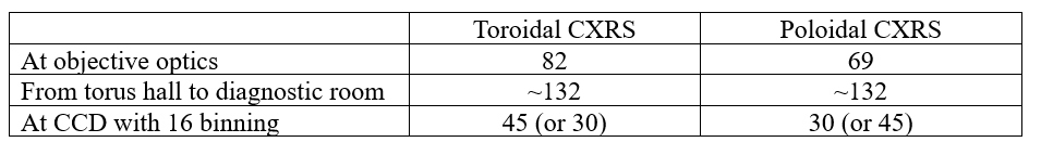
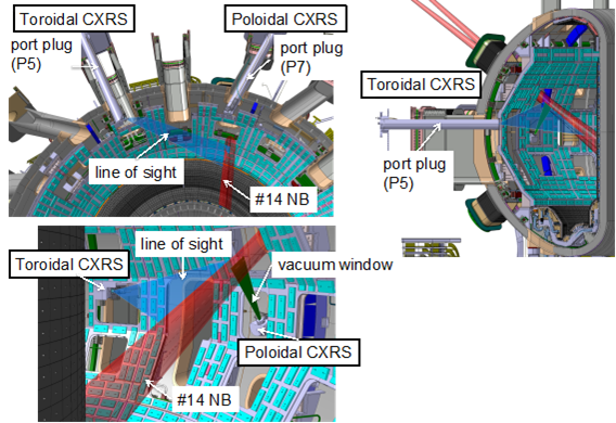
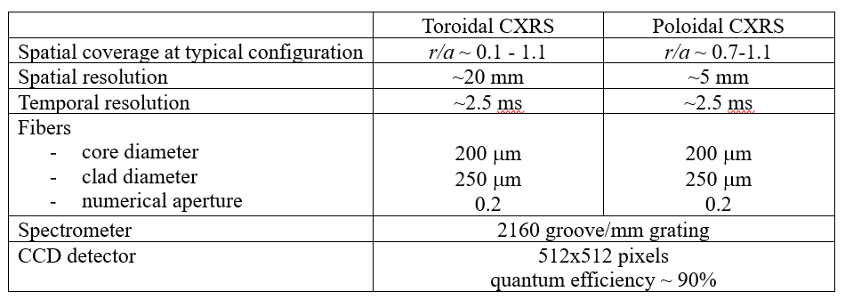
The CXRS diagnostics system is installed in ports P2, P5, P6 and P7. The ports P5 and P7 are allocated to view the neutral beam of #14 which is used as the CXRS diagnostic beam for both toroidal and poloidal measurements as shown in Figure 1. The ports P2 and P6 are allocated for measurement of the background spectrum only. The specifications of the CXRS system are shown in Table 1. The spatial coverage of the toroidal CXRS is from the plasma centre to the plasma edge. The channel pitch is about 20 mm with about 82 channels, which is almost the same as the spot diameter at the beam. The poloidal CXRS focusses on the edge region with higher spatial resolution of ~5 mm using 69 channels. The objective optics is designed to avoid crosstalk. About 132 optical fibers for each port, i.e. toroidal signal, toroidal background, poloidal signal and poloidal background, are routed from the torus hall to the diagnostic room. On the other hand, the number of channels, i.e. the number of radial positions, will be limited by the number of spectrometers and CCD cameras. Three sets of CCD camera and spectrometer are prepared. This will allow to measure 75 channels in total, for example, 45 channels for toroidal and 30 channels for poloidal measurements.
The optical fibers connected to the spectrometers and CCD cameras, in other word, the radial position to be measured, can be changed shot by shot. The numbers of measuring channels are summarized in Table 2. Signals from the plasma through the optics system are transferred to spectrometers and CCD cameras in a diagnostic room via two joint boxes, one is in the torus hall, another in the diagnostic room. The total length of the optical fibers from the objective optics to the spectrometers is about 120 m (~50 m in the torus hall, ~60 m between the torus hall and the diagnostic room, and ~10 m from diagnostic room to spectrometers).