Auxiliary Plant – Power Supply
The power supply system is a combination of those for the superconducting and control coils, the beam and EC heating and current drive systems, and power supplies for auxiliary plant. Pre-existing equipment has been re-used where possible, on a rearranged AC supply network.
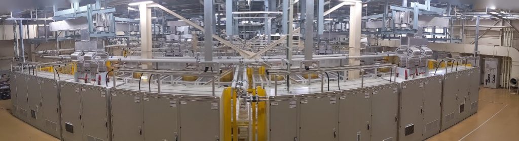
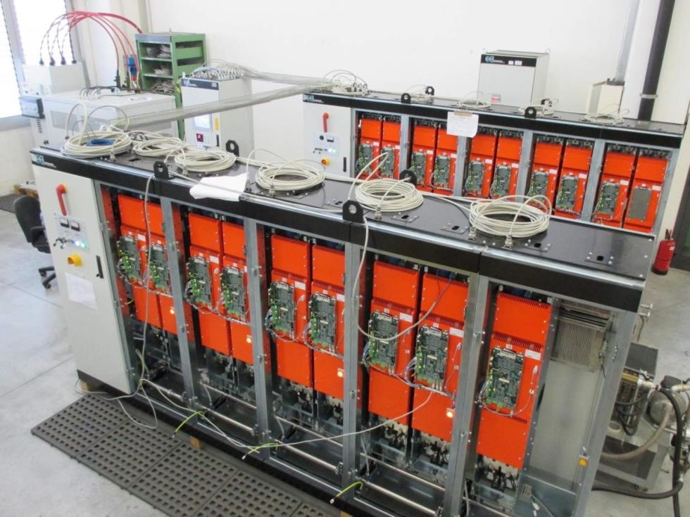
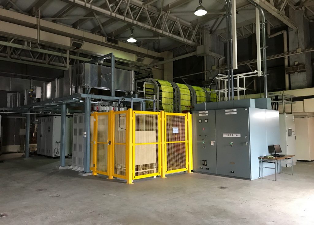
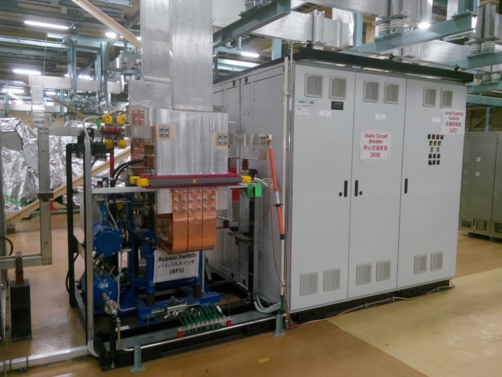
Toroidal Field Coil Circuit
The toroidal field coil circuit is composed of 18 superconducting coils connected in series and supplied by a single unidirectional ac/dc converter (TF Converter). The 18 coils are divided into three groups of six coils, interleaved with three quench protection circuits (QPC) assuring the protection of the toroidal field coils in the case of quench or other fault requiring a fast discharge of the coils.
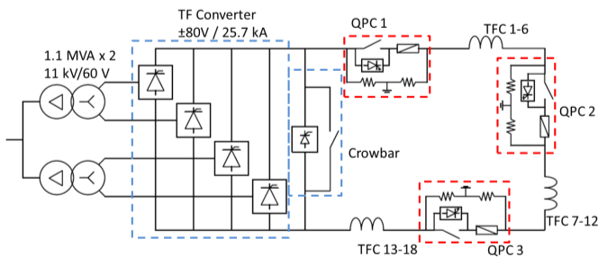
Typical operation of the TF coil power supply is that the TF coils are energized every day in the morning before the start of the plasma experiments, and discharged at the end of the day after the experimental period. The maximum time for ramp-up and ramp down of the nominal current is 25 minutes. In the case of a quench, the coil current is rapidly decreased to zero with the operation of the 3 QPC, dissipating the magnetic energy of more than 1 GJ stored in the toroidal magnets and assuring that the maximum I2t in the magnets after quench detection remains less than 4.6 GA2s.
Poloidal Field Coil Circuits
JT-60SA is provided with 10 superconducting poloidal field (PF) coils: 4 are placed in the innermost part of the vacuum vessel, together forming the Central Solenoid (CS1-4), and 6 are external as Equilibrium Field (EF1-6) magnets.
The main components of each PF coil circuit are a “base converter”, a “switching network unit (SNU)” or a “booster converter”, and a “poloidal QPC”.
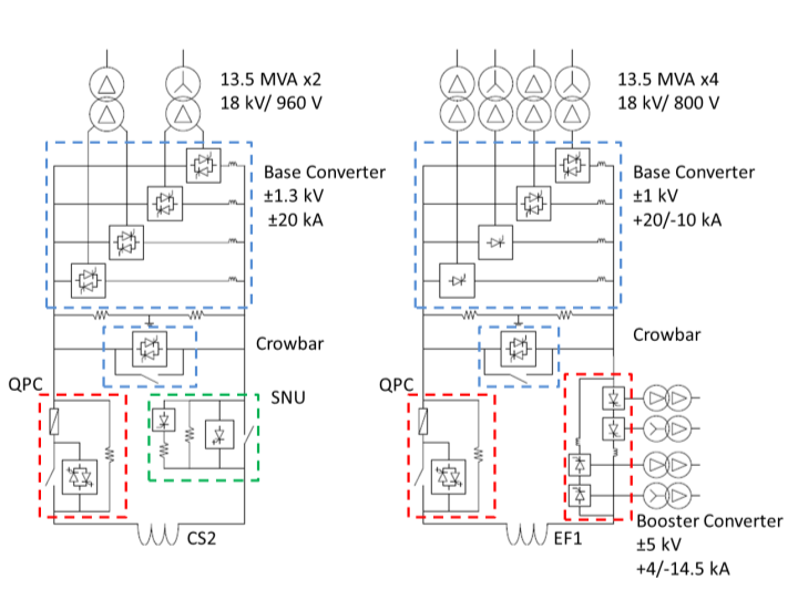
The base converter provides the nominal current value of ±20 kA with a duty cycle of 220 s/1800 s, supplying a nominal voltage of ±1 kV.
The SNU is able to generate up to the maximum voltage of -5 kV by inserting a breakdown resistor in the circuit when the nominal current of 20 kA is flowing.
The booster converter supplies a voltage of ±5 kV with a maximum current rating of +4 kA/-14.5 kA, for a maximum duration of few seconds.
The poloidal QPC assures the possibility of rapidly removing the magnetic energy stored in the coil in chase of quench or other fault, rapidly interrupting the ± 20 kA dc current with an applied voltage of less than 5kV.
Fast Plasma Position Control circuit
Two standard copper coils are installed inside the vacuum vessel to control fast variations of plasma position. To be able to regulate both the vertical and horizontal field against small plasma perturbations such as minor disruptions, they are supplied by two independent fast plasma position control converters. These converters are able of working in four quadrants (i.e. with all combinations of positive or negative voltages and currents), with a rating of ±5 kA and ±1 kV for a duty cycle of 140 s / 1800 s.
4. Resistive Wall Mode Control Power Supply:
Resistive wall mode instabilities are actively controlled by 18 sector coils, installed inside the vessel, in front of the stabilizing plate, and individually supplied by 18 independent converters. The converters have to be able to work in 4 quadrants with a duty cycle of 100 s/1800 s, providing a current of ±300 A with challenging requirements in terms of dynamics. In fact they are required to have a current bandwidth of 3 kHz and a maximum latency of 50 μs.