Auxiliary Plant – Cryogenics
The cryogenic system supplies helium at different cryogenic temperatures to the following components in the JT-60SA device and its connected Valve Boxes (VB) and Coil Terminal Boxes (CTB).
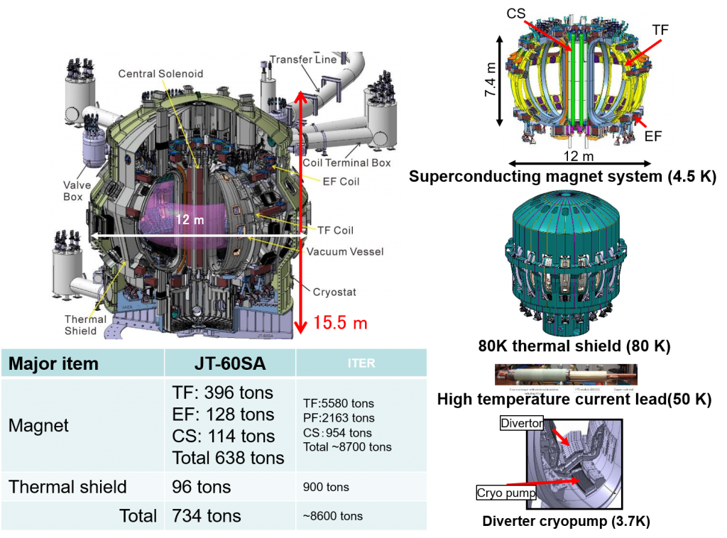
- The thermal shields (TS) protecting the magnet system are kept between -90K (-183°C) (80 K to 100 K) by a circulation of helium gas between 80K and 100K at a pressure around 15 bar.
- The high temperature current leads (HTS CL), which conduct the ambient temperature busbars to the low-temperature superconducting coils are supplied with a gas flow at 50 K (-223 °C) and 4 bar
- The superconducting magnet system composed of 18 Toroidal Field (TF) coils, 6 Equilibrium Field (EF) coils, 4 modules for the Central Solenoid (CS) and their respective structures are cooled by a circulating flow at 4.4 K (-269°C) and 5 bar.
- The divertor cryopumps, which are used to evacuate neutralised plasma, are cooled by single phase helium at 3.7 K (-270°C):
The total refrigerator capacity of the cryoplant is equivalent to a heat load of about 9 kW at 4.5 K. This capacity includes a contingency of about 15 % against the estimated loads from the individual components.
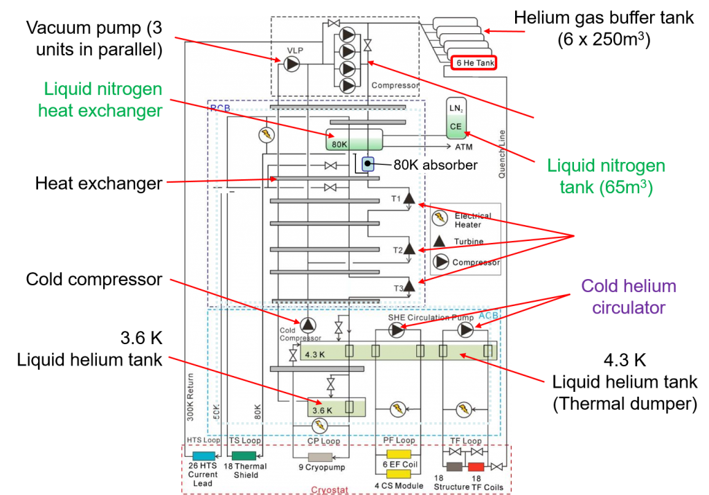
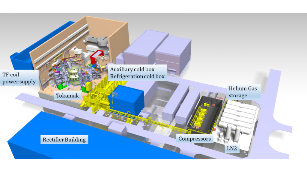
The cryogenic system is composed of the following main parts as schematically shown in the figure above:
- a system of eight parallel warm screw compressors with sound protection, a common oil and water removal system, pressure control and a gas management system; during full power operation, the compressors consume 2.4 MW of electrical energy; additional vacuum pumps lower the pressure in the subcooler to reach a temperature of 3.7 K;
- a refrigerator cold box (RCB) with the main heat exchangers, liquid nitrogen precooling, integrated 80 K purifier, and three gas lubricated expansion turbines provide the necessary refrigeration at different temperature levels;
- an auxiliary cold box (ACB) including a 7000 l liquid helium damper, to absorb the pulsed heat loads during plasma operation, a subcooler for pre-cooling the cryopump coolant, a cold compressor to sub-cool the liquid helium and two cryogenic pumps to circulate approximately 2 kg/s of supercritical helium through the coils and their structures; integrated heaters allow simulating the maximum expected heat loads during acceptance tests;
- instrumentation and a local control system allow autonomous operation of the refrigerator as well as remote control by the central JT-60SA control system;
- a gas storage and distribution system comprising six warm helium storage vessels with a total volume of 1500 m³, a liquid nitrogen storage, cryogenic transfer lines, and warm interconnecting pipework; one of the storage vessels is modified with a dedicated inlet nozzle to recover cold helium gas after a quench or a fast discharge of the superconducting coils;
- auxiliary equipment such as cooling towers for the compressors and turbines, a central instrument compressor and high vacuum pumps for the RCB and ACB and the cryolines.
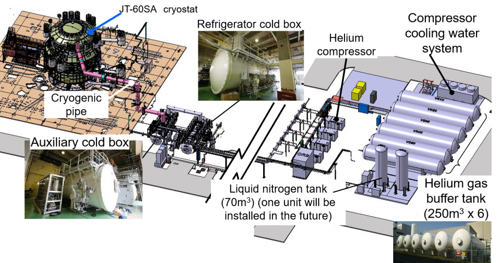
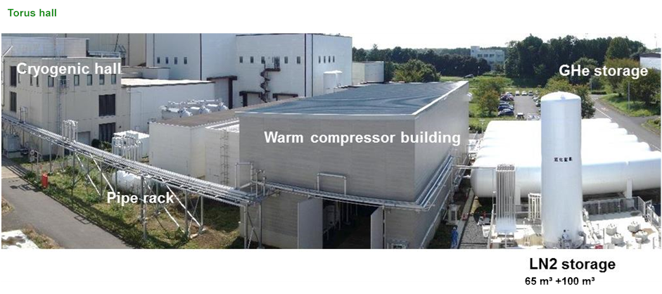
For the compressor station, a new building was erected on the west side of the JT-60SA experimental building. The cryogenic hall neighbouring the torus hall accommodates the RCB, ACB and the subcooler vacuum pumps. A large, 60 m long and 1 m diameter transfer line connects the nine cryolines from the ACB to the tokamak. The cooling towers, the gas storage vessels and the liquid nitrogen storage are located next to the compressor hall as shown below.
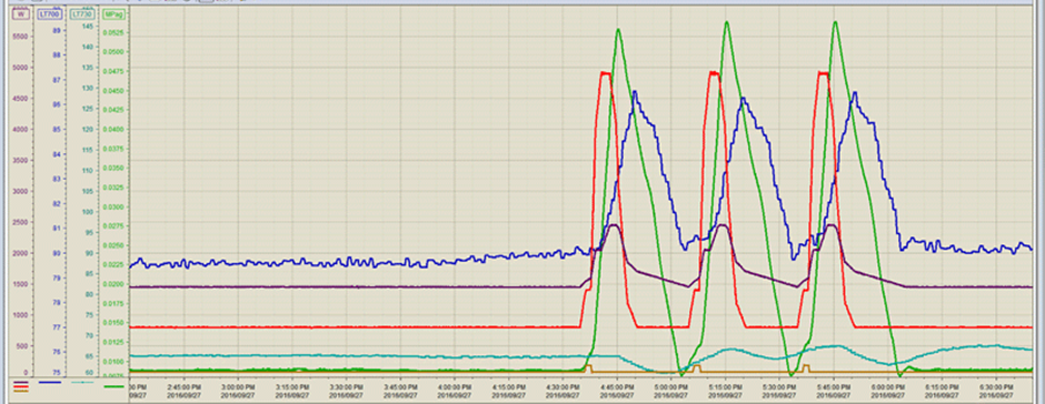
The plant was constructed and installed by Air Liquide Advanced Technology, France under contract of Commissariat à l’Energie Atomique et aux Energies Alternatives (CEA). In September 2016, acceptance of the plant was achieved by applying a sequence of 3 simulated plasma pulses with the specified nominal heat load as shown below.
Since then the focus has been on training the members of the Japanese operating team in the management and maintenance of the facility, and in preparing for operation.
")


