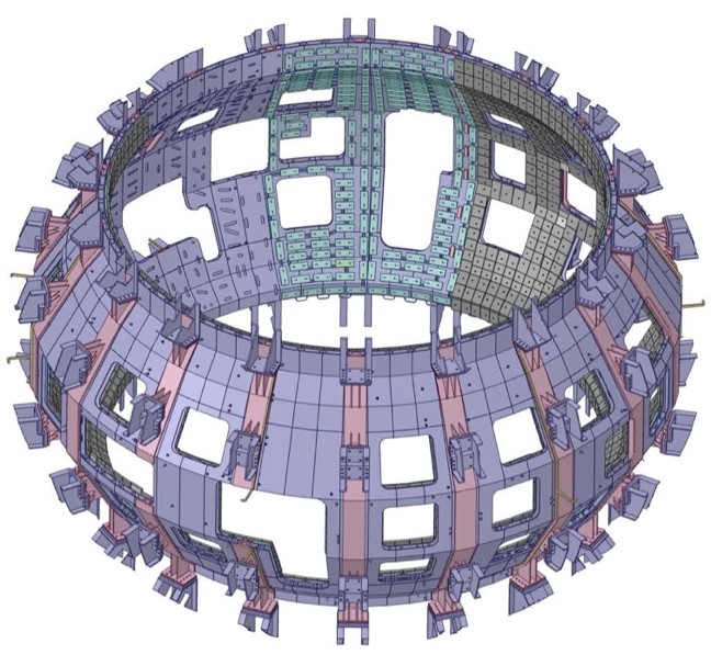
Tokamak – In-Vessel Components
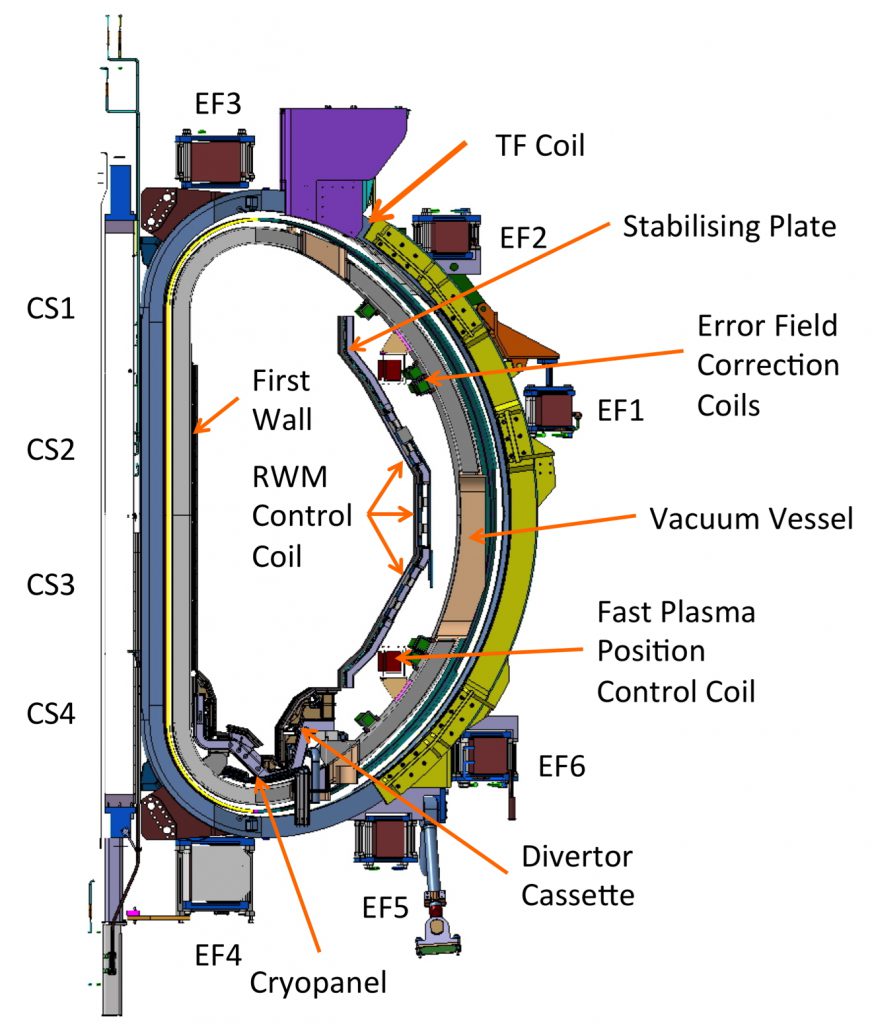
The major in-vessel components are
- divertor cassettes,
- the inboard first wall,
- the stabilizing baffle plate and outboard first wall,
- fast plasma position control coils,
- sector coils for resistive wall mode (RWM) control,
- magnetic diagnostic coils,
- error correction coils,
- cryopanels for particle pumping.
For the first phase of operation only a lower divertor has been installed, optimised to allow ITER-shape and high-triangularity plasmas. A fully equipped upper divertor is planned at the start of the extended research phase. During that phase too, once operation is better understood, a mono-block type CFC divertor armour is planned for the outboard side able to withstand a heat load of ~15 MW/m2. During the initial research phases, due to the smaller expected heat load, a flat tile type divertor armour will be used instead. The use of metallic divertor tiles is also being considered for the later research phases.
Full remote handling compatibility will be built up during the initial phases of operation, ready for full remote divertor tile replacement before the extended research phase.
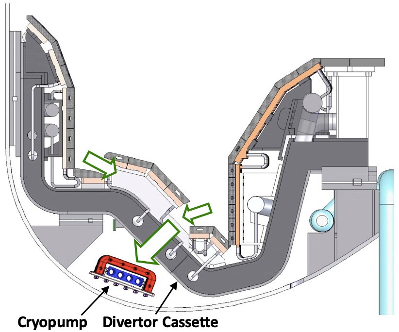
Cryopanels are installed behind the divertor to improve pumping capability. A water-cooled chevron is installed in front of the pumping hole to reduce heat load on the cryopanels.
Two in-vessel coils are used for fast plasma position control. Independent power supplies are connected to each coil block to control vertical and horizontal field at the same time.
The primary function of the stabilizing baffle plates is to enhance the ideal beta limit and to improve plasma positional stability. They have been designed as a double-wall structure and are covered with a bolted carbon-armoured first wall.
Sector coils for the RWM control have been installed around the openings of the stabilizing baffle plate facing the plasma to minimize the control response time. Since each sector coil has its own current leads, the magnetic field mode of m/n = 3/1 or 3/2 can be controlled depending on the configuration of the power supply connections.
Saddle coils (rectangular loops on the vacuum vessel) are included to manage slow or non-rotating MHD modes arising from any slight field misalignments after coil assembly. Three coils are located polodally at six toroidal locations.
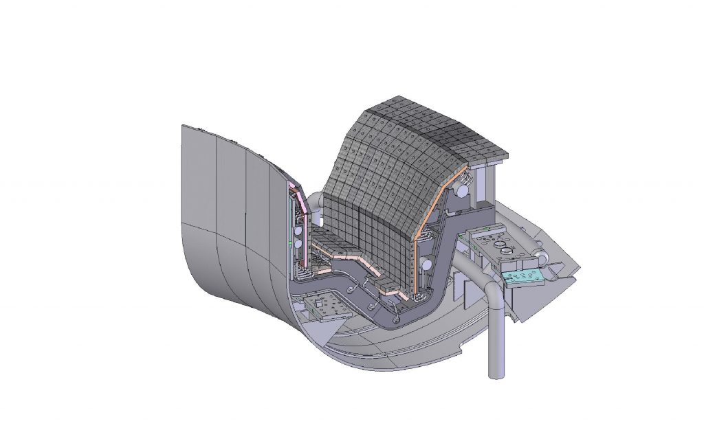
Lower Divertor
The divertor is installed at the bottom of the vacuum vessel. All plasma-facing components (PFCs) for the lower divertor are water-cooled for high-power and long-pulse heating. Carbon armour tiles bolted on water-cooled copper alloy heatsinks are applied to remove heat loads. Divertor cassettes with integrated coolant pipes for PFCs will be introduced. Each cassette covers 10 degree in the toroidal direction. PFCs on the divertor cassette are designed as replaceable modules.
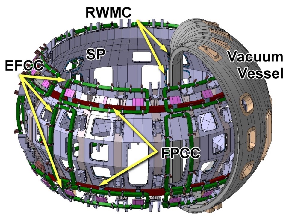
Stabilizing plate The main purpose of the stabilizing plate (SP) is to protect the in-vessel components as first wall at the outboard side, and to stabilize vertical displacement events (VDEs) and ideal MHD instabilities in high beta plasmas. These plates have a double shell structure (10 mm thickness each) and a rigid support with trusses to provide adequate strength against electromagnetic forces originating from eddy currents.
Fast plasma position control coil (FPPC)
The FPPC coil system consists of two circular normal-conducting coils (upper and lower coil). These two coils can provide independent control of vertical and horizontal field. The radius of the current center is 3,975 mm. The maximum operation current is 5.0 kA for a period of 25 sec.
Resistive wall mode control coil (RWMC)
Sector coils to control resistive wall modes (RWMs), which is one of the magnetohydrodynamic instabilities, are installed on the side of the stabilizing baffle plate facing to the plasma. Since each sector coil has its own current leads, the magnetic field mode of n = 1 to 3 can be controlled.
Error field correction coils (EFCC) The superconducting coils (TFC, EFC and CS) are manufactured and assembled with finite tolerances. These deviations from their nominal size and position produce asymmetric components of equilibrium magnetic field, so-called, error fields. In particular, singular toroidal deviations, so-called the n=1 component, could strongly affect the stability of MHD modes. To avoid destabilization of MHD modes by the n=1 component, error field correction coils (EFCCs) are installed on the vessel surface behind the stabilizing baffle plate The EFCC are composed of three sets of 6 rows, arranged as upper, middle and lower coils. These coils have individual power supplies. The EFCCs are also utilized to create resonant magnetic perturbations (RMPs) to suppress and mitigate heat loads by edge localized modes (ELMs).
Divertor Cryopumps The divertor cryopump is installed to evacuate neutralized hydrogen or deuterium fuel, seeding gases (N2, Ar). The cryopump is separated into 9 identical units and located in the volume underneath the divertor dome. Each cryopump unit consists of adsorption surfaces (cryopanels) cooled by 3.7 K supercritical helium, and a thermal radiation shield surrounding the cryopanel made of a base plate and an inlet baffle cooled at about 80 K. One cryopump unit covers four 10-degree divertor cassettes. To protect the thermal radiation shield from the plasma and from stray radiation by electron cyclotron waves, the pumping aperture in the divertor is covered by a water-cooled baffle. In order to efficiently pump helium by cryosorption, the cryopanels are covered with activated charcoal granules.