Tokamak – Magnet Shared Components
These components provide the interface between the magnets and their services – cooling, power and instrumentation – and are often of a common design for all the magnet systems. They include:
- current feeder lines and their structural support,
- cryogenic supply lines (cryolines) including cryostat feed-throughs, servicing the conductors, magnet structure or feeders,
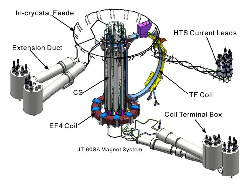
- current leads connecting coil conductor and feeder lines – for JT-60SA made from high temperature superconductor to minimise cooling requirements,
- coil terminal boxes (housing the current leads) and cryogenic valve boxes (for control of cryolines),
- coil terminal boxes (housing the current leads) and cryogenic valve boxes (for control of cryolines),
- quench relief valve assemblies,
- instrumentation, cabling and control cubicles.
The toroidal field coils use three separate power supplies, each feeding six coils, whereas the four central solenoid coil modules and the six equilibrium field coils have one power supply each. All the coils use high temperature (~50K) superconductor (HTS) current leads to connect to the power supplies. These 26 leads are being manufactured by KIT in Karlsruhe (for Germany).
The procurement of the remaining items (by Japan) is due to begin in 2014.
HTS Current Leads (CL)
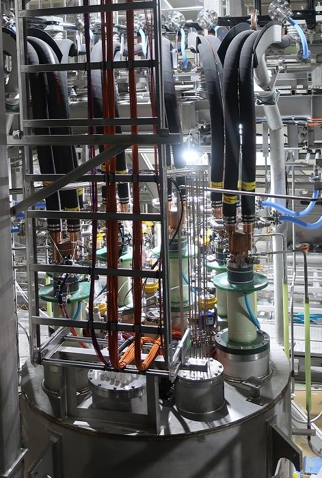
The total number of 26 HTS CL were designed, manufactured and tested by Karlsruhe Institute of Technology (KIT), Germany. For the tests at cryogenic temperatures and nominal current, always two HTS CL were connected by a superconducting shunt in a dedicated test facility.
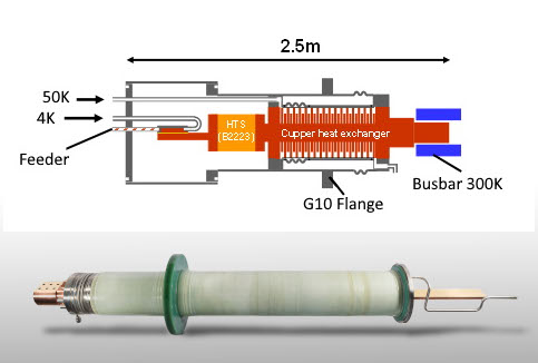
The design principle of the HTS CL together with a photo of a real current lead is shown in Fig. 1.
The current from the bus bars at ambient temperature is entering the current lead through a clamped contact and passing along a high-conductive copper heat exchanger, thereby bridging the temperature range down to -213 °C (60 K). The conductive heat along the copper and the ohmic heat produced by the current is absorbed by a small flow of helium entering at a temperature of -223 °C (50 K). In order to reduce the conductive heat to the cryogenic components further, a high temperature superconductor (HTS) section with zero resistance for the current but low thermal conductivity is soldered to the lower end of the heat exchanger. The cold contact of the current lead has a resistance of only a few nano-Ohms and feeds the current through a superconducting feeder to the coil terminal. During a fast discharge of the magnets, the current leads may reach high voltages of a few kilo-Volts. Therefore, the current leads are mounted at the Coil Terminal Boxes through insulating epoxy (G10) flanges (see Fig. 2)