
CO2 polarimeter system
The tangential CO2 laser interferometer has been installed and operated in the integrated commissioning. To complement the interferometer, the polarimeter using two-color lasers with the wavelength of 10.59µm and 9.25µm and Photoelastic Modulators (PEMs) is procured. The target specifications of the CO2 laser polarimeter is shown in Table 1. The CO2 lasers used in the interferometer-polarimeter system have 6 hours stability in wavelength without mode hopping. Moreover, a cavity mode control system has been investigating for the wavelength stability. In the cavity mode control system, a piezo element incorporated in a laser cavity is controlled according to the measured wavelength.
| Temporal resolution | ~4 ms |
| Polarization angle resolution | ~± 0.05 degree |
| Channels | 1 (tangential, P8-P1) |
Figure 1 shows the system configuration of CO2 tangential interferometer/polarimeter. While most of the components for polarimeter can be shared with those for interferometer, some individual components such as PEMs, detectors and data acquisition system are required.
Visible TV camera system
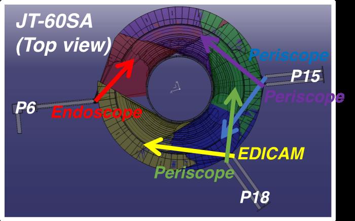
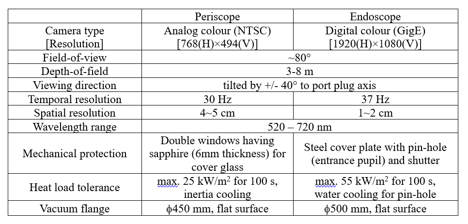
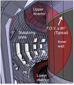
The main role of the visible TV camera system is to monitor the Plasma Wall Interactions (PWIs) at the divertor, limiter and first wall, where is mostly covered by the carbon tiles (1 piece: 12 cm x 7 cm). Thus, the field-of-view (FoV) for each viewing chord is in the order of 80°, covering a wide area of the vacuum vessel, such as inner wall, outer stabilizing plate, and upper/lower divertor regions. The visible TV camera system consists of one endoscope at P6 horizontal port, two periscopes at P15 horizontal port, one periscope at P18 horizontal port and one EDICAM at P18 horizontal port as shown in Figure 1. The light-guide systems is equipped under each port-plug for illuminating inside the vacuum vessel without plasma emission, using a fiber optics connected to the metal halide lamp (375 W).
Infrared TV camera systems
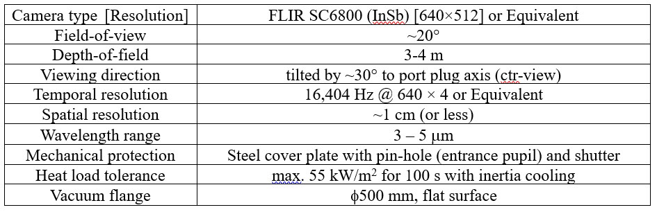
Two types of infrared TV (IRTV) camera systems will be prepared. One having wide-angle FoV covering a wide area in vacuum vessel is used for monitoring the in-vessel components such as inner wall, outer stabilizing plate, and upper/lower divertor regions. The system is installed at P6 horizontal port as a part of the endoscope. The other system having narrow-angle FoV is used for monitoring the divertor tiles and the system is installed at P15 horizontal port. The specifications of the IRTV camera system for wide-angle FoV and narrow-angle FoV (or divertor) are shown in Table 1 and 2, respectively.
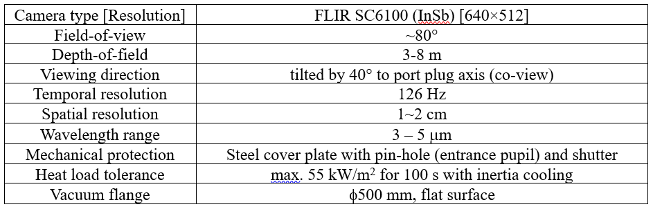
In order to image a large section inside the vacuum vessel (both in poloidal and toroidal directions), the endoscope system using mainly reflective optics provides a wide-angle view as shown in Figure 1.
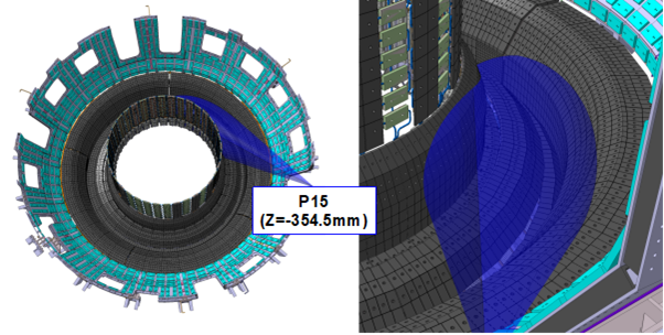
In order to image the divertor strike points (such as the V-shaped corner) with high spatial and temporal resolution, the endoscope system using mainly reflective optics provides a narrow-angle view as shown in Figure 2.
Electron cyclotron emission diagnostics system
A port plug with mirror box is installed at P11 horizontal port. The sight line is horizontal and passes the centre of the plasma (Z = 0). To reduce the visual angle, a mirror box containing a pair of parabolic mirrors is installed between the viewing port and the end of the waveguide. Design calculations using the finite-difference time-domain method taking into consideration the size of the ECE port plug showed that the full width at half maximum of a Gaussian beam launched from the ECE port is about 10 cm at the plasma centre (the width is related to the visual angle). The total waveguide length from the diagnostic port to the ECE diagnostic room is about 60 m.
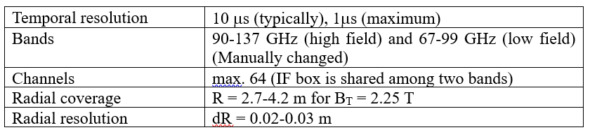
For detection systems, a heterodyne radiometer using narrow-band filters and Schottky diode detectors is used for the measurement of JT-60SA plasmas. In the typical operation conditions of JT-60SA at the toroidal field of 1.7 – 2.25 T, second harmonic ECE ranging from 70 to 140 GHz will be used for temperature measurement. The range corresponds to –0.2 < r/a < 1 (the negative value represents the higher magnetic field region with respect to the magnetic axis). Channel spacing of a few cm is necessary for the heterodyne radiometer to measure the detailed structure of instabilities such as magnetic islands associated with neoclassical tearing modes (NTMs). A sampling rate of typically tens of a microsecond is desired for the measurement of instabilities such as NTMs, sawteeth and ELMs. The specification of the ECE diagnostic is shown in Table 1. Relative calibration between channels will be performed using a radiation source.
Divertor Langmuir probe system
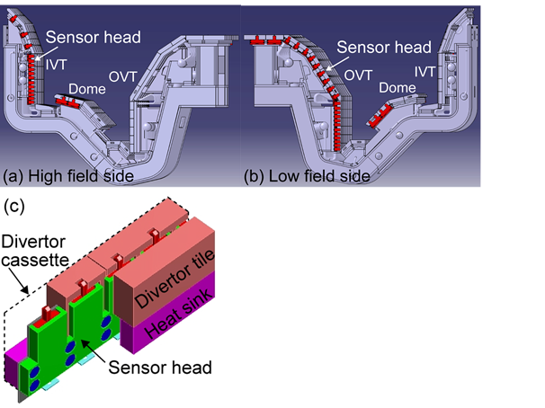
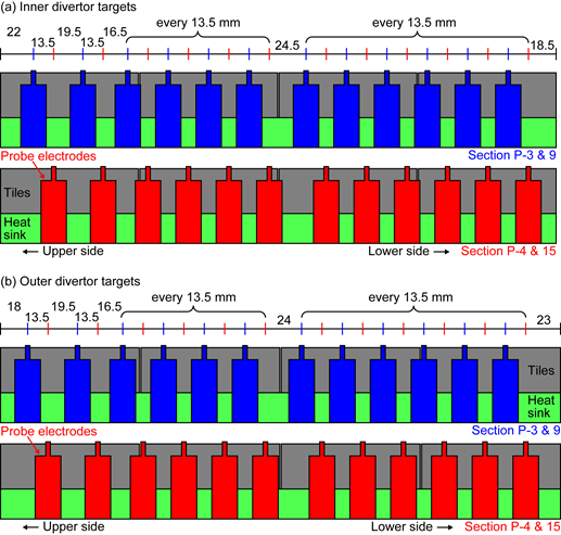
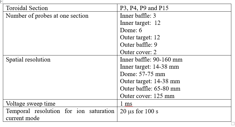
A divertor Langmuir probe system for the measurement of plasma parameters in the divertor region such as electron density (ne), electron temperature (Te), floating potential (Vf) and ion saturation current (Isat) will be prepared. The divertor Langmuir probes comprise sensor heads, mineral insulated (MI) cables and a data acquisition system. As shown in Figure 1, the sensor heads are installed on the edge of the JT-60SA divertor cassettes to facilitate replacement of those. The sensor heads will be installed in four toroidal sections. Detected current is transported to the data acquisition system by means of MI cables. Figure 2 shows the spatial resolution of the Langmuir probes on the inner and outer divertor target. The Langmuir probe on Section P-3 and 9 are installed 13.5 mm above those on Section P-4 and 15. Simultaneous measurement, for example, Section P-3 and 4, improves the minimal spatial resolution to 13.5 mm. The Langmuir probes on the other position such as the inner and outer baffles, dome and outer cover are installed at the same poloidal position for the different toroidal section. The specifications of the Langmuir probes are shown in table 1.
Bolometer system
A bolometer system for the evaluation of the total of radiation power from the plasma and its spatial distribution will be prepared. The radiation power is also used for real-time feedback control of the plasma. In JT-60SA a 4-channel resistive bolometer system is applied to the radiation power measurement. Two types of bolometer heads are installed at P18 upper and horizontal port, and P16 lower diagnostic slit: one is the head with a thinner absorber for lower energy radiation from the plasma with the electron temperature <7.9 keV and the other is with a thicker absorber for higher energy radiation from the plasma with higher electron temperature <13.5 keV such as Scenario #2. The specifications of the bolometer system are summarized in Table 1.
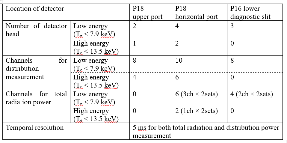
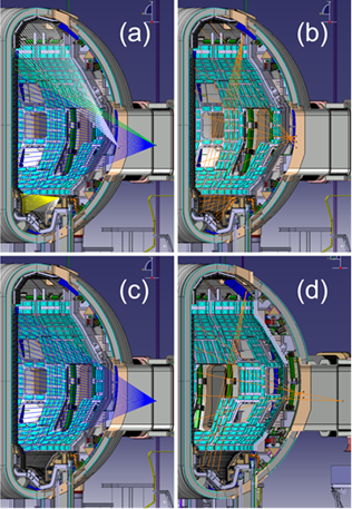
Figure 1 (a) and (b) show viewing chords of the total radiation power and the radiation power distribution measurement for lower energy radiation, respectively. Total and distribution of the radiation power are independently evaluated by different detectors. The viewing chords are bundled into five detectors using multi-aperture type bolometer system (3 in horizontal port and 2 in diagnostic slit), as can be seen in the different colors in Figure 1 (a). The rest of detectors are divided into the radiation power distribution measurement as shown by each line in Figure 1 (b). Figure 1 (c) and (d) show viewing chords of the total radiation power and the radiation power distribution measurement for higher energy radiation, respectively.
12 bolometer channels (6 channels are for redundancy) which are specialized for an accurate measurement of the total radiated power with a method of weighted summation will be installed. The specialized bolometer channels are designed to minimize the error of the measurement of the total radiated power with few number of bolometer channels and viewing angle. The specialized bolometer channels are designed to bundle multiple sight lines into a bolometer detector. This specialization is based on uniform etendue by different aperture size among bundled lines of sight and uniform viewing volume per unit length of lines of sight by optimization of installation position. With this specialized bolometer, the total radiated power can be evaluated with less than 10 % error.
Visible spectrometer for divertor and Dα emission monitor systems
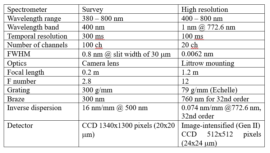
The visible spectrometer for divertor system measures the two-dimensional distribution of emissions in the visible range from the lower divertor mainly to investigate the behaviour of fuel particles and impurities, particularly from the viewpoint of atomic and molecular processes. Because the spatial distribution of the emission is complicated in the divertor region, a two-dimensional measurement is required. Hence two dimensional arrays of viewing chords will be prepared: one is a vertical array installed at P6 upper vertical port and the other is a horizontal array installed at P6 lower vertical port.
For the optics of the vertical and the horizontal arrays, achromatic lenses are used to suppress the axial chromatic aberration and to allow to measure spectra in a wide wavelength range from 350 nm to 800 nm. With the achromatic lenses, the spot size for the horizontal array is evaluated to be 10 mm in this wavelength range. Emission from the divertor plasma through an object window is focused by the lenses onto optical fibers and is transmitted to a diagnostic room. In the diagnostics room, spectra are recorded with the survey spectrometer and the high-resolution spectrometer. The specifications of these spectrometer are shown in Table 1.
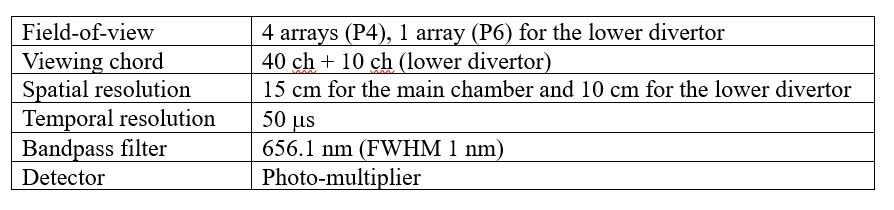
The Da emission monitor system measures poloidal distribution of Da emission intensities mainly for the purpose of evaluating particle recycling flux from the first wall and the upper and the lower divertor plates, and monitoring ELM activities. Four arrays of viewing chords are prepared at P4 lower oblique port. The lower three arrays cover a field of view of 28º each while the upper one covers 20o. Each array has 10 viewing chords, resulting in a spatial interval of 15 cm at the inboard side of the vacuum vessel. The optics is designed such that the focusing points are 2.5 m – 4.0 m away from the entrance pupils at the end of P4 lower oblique port. In addition, 10 viewing chords for the lower divertor are shared with those for visible spectrometer for the divertor. Da Emission from the plasma through an object window is focused by lenses onto optical fibers and is transmitted to the diagnostic room. In the diagnostics room, photomultipliers detect the Da emission filtered with interference filters with a bandwidth of 1 nm and a transmittance peak wavelength of 656.1 nm. The specifications of the Da emission monitor are shown in Table 2.
Vacuum Ultra Violet (VUV) spectrometer system
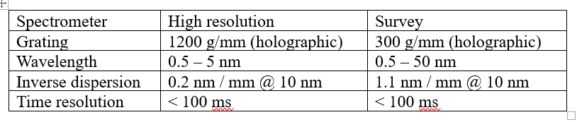
A VUV spectrometer for monitoring the brightness of line emission from light impurities such as carbon and oxygen, and also from metal impurities for safe operation of the JT-60SA device, will be prepared. The VUV spectrometers are installed at P10 horizontal port and view the plasma horizontally without viewing the neutral beams directly. Two grazing incidence spectrometers will be prepared: One spectrometer (high resolution) covers a wavelength range of 0.5 – 5 nm with a holographic grating having 1200 grooves/mm, and the the other spectrometer (survey) covers a wavelength range of 0.5 – 50 nm with a holographic grating having 300 grooves/mm. The light dispersed by these gratings is focused on a flat plane with a width of ~ 26 mm. On the flat focal planes, a CCD camera with an imaging array of 1340 x 1300 pixels having a size of 20 x 20 mm detects the dispersed light. The object optics with a viewing chord similar to that of the VUV spectrometers, for example, by using zeroth order diffraction (reflection) light, is prepared for an absolutely calibrated visible spectrometer for the purpose of relative calibration with a branching ratio method. The specifications of the VUV spectrometers are shown in Table 1.
Thomson scattering system
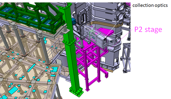
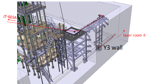
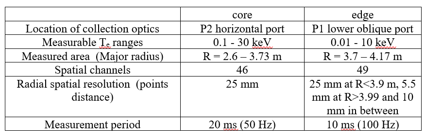
The YAG laser Thomson scattering system consists of core system installed at P2 horizontal port and edge system installed at P1 lower oblique port. Figures 1 and 2 show the schematic of P2 stage and Y3 laser stage for Thomson scattering, respectively. These stages are designed to keep the same stiffness as the stage used in JT-60U.
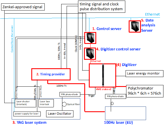
Figures 3 shows the data acquisition system and the laser control system. Two YAG lasers are fired synchronized with the timing provided by timing provider. Scattered lights by plasma are transferred to laser room II by bundled fibers and then fed to polychromators. In Figures 3, 96 polychromators are procured by F4E and components with number (1~5) are procured by QST. Output signals from polychromators (6 outputs for each measured point) are acquired by digitizers. Each digitizer has 32 ch inputs, and 19 digitizers are prepared where 10 digitizers are prepared for edge system and 9 digitizers are prepared for core system. The target specifications of the core Thomson scattering system are shown in Table 2.
Charge exchange recombination spectroscopy (CXRS) diagnostics system
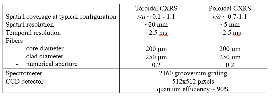
The CXRS diagnostics system, for the measurement of the ion temperature, toroidal rotation, poloidal rotation, carbon impurity density profiles based on the Doppler broadening, spectral shift and intensity of the light emitted by charge exchange recombination reaction between the carbon impurity ions and neutral beams, will be prepared.
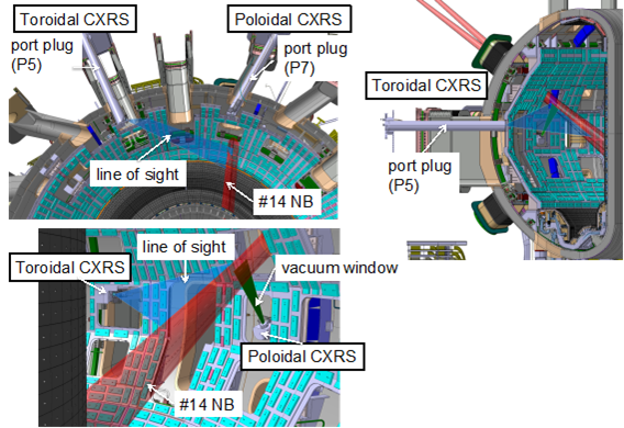
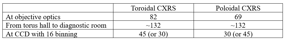
The CXRS diagnostics system is installed in ports P2, P5, P6 and P7. The ports P5 and P7 are allocated to view the neutral beam of #14 which is used as the CXRS diagnostic beam for both toroidal and poloidal measurements as shown in Figure 1. The ports P2 and P6 are allocated for measurement of the background spectrum only. The specifications of the CXRS system are shown in Table 1. The spatial coverage of the toroidal CXRS is from the plasma centre to the plasma edge. The channel pitch is about 20 mm with about 82 channels, which is almost the same as the spot diameter at the beam. The poloidal CXRS focusses on the edge region with higher spatial resolution of ~5 mm using 69 channels. The objective optics is designed to avoid crosstalk. About 132 optical fibers for each port, i.e. toroidal signal, toroidal background, poloidal signal and poloidal background, are routed from the torus hall to the diagnostic room. On the other hand, the number of channels, i.e. the number of radial positions, will be limited by the number of spectrometers and CCD cameras. Three sets of CCD camera and spectrometer are prepared. This will allow to measure 75 channels in total, for example, 45 channels for toroidal and 30 channels for poloidal measurements.
The optical fibers connected to the spectrometers and CCD cameras, in other word, the radial position to be measured, can be changed shot by shot. The numbers of measuring channels are summarized in Table 2. Signals from the plasma through the optics system are transferred to spectrometers and CCD cameras in a diagnostic room via two joint boxes, one is in the torus hall, another in the diagnostic room. The total length of the optical fibers from the objective optics to the spectrometers is about 120 m (~50 m in the torus hall, ~60 m between the torus hall and the diagnostic room, and ~10 m from diagnostic room to spectrometers).
Soft X-ray intensity measurement system
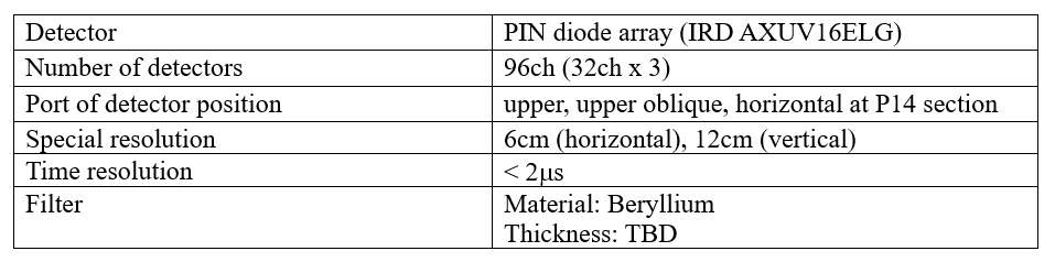
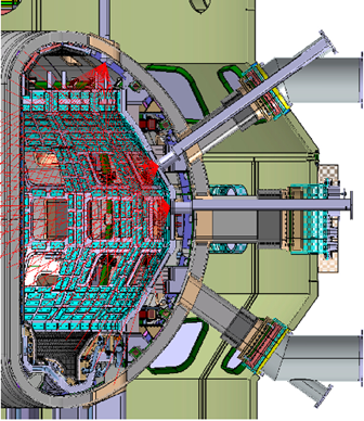
The soft X-ray intensity measurement system, for the measurement of the line integrated soft X-ray emission, which mainly reflects the electron density and temperature, in order to know the approximate plasma pressure profile, the internal structure of MHD events and the impurity transport, will be prepared. Two sets of 16 channel PIN diode arrays will be installed in the each of the P-14 upper, upper oblique, and horizontal port as shown in Figure 1 in order to measure the soft X-ray intensity profile. The diode arrays with Beryllium filter are fixed in the vacuum condition. Using these profiles from 96 viewing chords, the computer tomographic (CT) reconstruction technique can be applied. The specifications of these spectrometer are shown in Table 1.
Motional Stark effect (MSE) polarimeter system
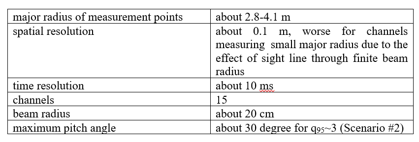
The MSE polarimeter system for the measurement of pitch angle of magnetic field line to evaluate the safety factor (or current density) profile through equilibrium reconstruction will be prepared. The MSE polarimetry is installed at the P17 horizontal port for viewing the tangential #8B beam (~85keV, P-NB), which is injected slightly off-axis counter (co) direction to the plasma current in lower-single-null configuration. The NB#8B is injected downward. Since the diagnostic beam will pass slightly off-axis, r/a < ~0.15-0.2 cannot be measured in standard configuration, as shown in Figure 1 (a). The sight line becomes almost tangential to the toroidal field when viewing from the P17 horizontal port, which gives the best spatial resolution. The beam radius is about 20cm about the measurement points. Calibration of observed polarization angle will be done by the injection of the diagnostic beam into the machine with D2 gas.
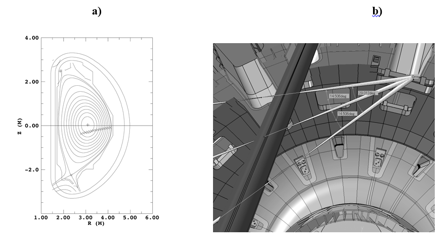
The polarimeter consists of mirrors, lenses, a pair of photo-elastic-modulators (PEMs), and a linear polarizer. About 20 optical-fibres (core diameter of 0.4mm; about 120m length) will be used for a single spatial channel. The diameter of the 20-fibre-bundle image across the diagnostic beam will be about 10cm, depending on spatial channel. Figure 2.14-1 (b) shows the expected field of view (FOV) of the MSE optics. The main region of the field of the view is in the lower-field-side, where attenuation of the diagnostic beam is small. The measurement points will cover R ~ 2.8-4.1 m. The specifications of the MSE polarimeter are shown in Table 1.
Neutron monitor system
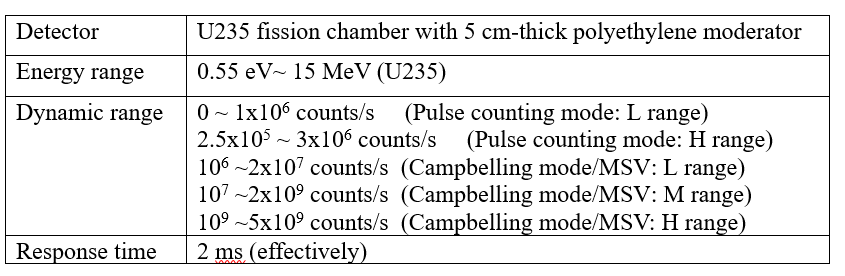
The neutron monitor system for monitoring the fusion performance and measuring neutron yields to meet the requirements from nuclear license will be prepared. The time-resolved volume-integrated neutron-emission rate (neutron yield) will be estimated from a neutron count rate by a detector using a U235 fission chamber (FC). Based on the nuclear license, three identical sets of neutron monitor are installed for redundancy, while two sets should be always active during deuterium plasma operation.
Each set consists of a FC detector, a preamplifier, a signal processing unit and five isolation amplifiers. The FC detector will be installed at R = 6.5m inside short port plugs installed at P6, P10 and P18 horizontal port sections. A signal from a FC detector is fed into a preamplifier placed near the cryostat and then fed into the signal processing unit and five isolation amplifiers installed inside a shield box located on the basement floor. The processed signals are transferred to digitizers, which are a part of SCSDAS outside the torus hall. The system is calibrated by moving a strong Cf neutron source inside the vacuum vessel in toroidal direction.
Table 1 shows the specification of the neutron monitor system. It is expected that the neutron yield can evolve by 9 decades in a high performance discharge. In the current design, the system can measure 2.5×10¹⁷ neutrons/s at maximum. The U235 FC detector, which is an ionization chamber whose wall is coated by fissile material (U235), can cover this dynamic rage. The large charges generated by the fission reactions allow to use it in the Campbelling mode. An appropriate moderator is necessary since the U235 FC detector is not sensitive to high-energy neutrons, i.e. of ~2.45MeV by DD reactions and of ~14MeV by DT reactions. To detect these high-energy neutrons a 5 cm thick polyethylene moderator is used as in JT-60U. The wide dynamic rage of the FC detector will be covered by the signal process unit with the pulse counting function and the Campbelling, or mean-square-voltage (MSV), function. To cover the full range two counter units with different but overlapping ranges are used. The Campbelling function is also secured by three processing units which cover different ranges with overlaps. In addition, the pulse counting function and the Campbelling function have an overlap.
Neutron profile monitor system
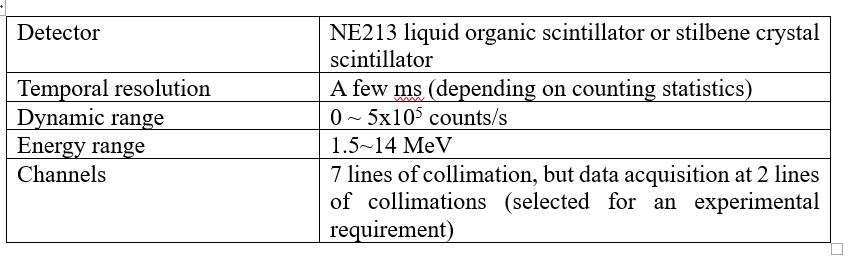
The neutron profile monitor system for the measurement of a line-integrated neutron emission profile will be prepared. An NE213 liquid organic scintillator or a stilbene crystal scintillator will be used as a detector because of its better sensitivity and fast response.
A digital signal processing method for neutron-gamma signal discrimination developed in JT-60U is used in JT-60SA. The detected pulses are post-processed concerning pulse-shape and pulse height. The radial neutron collimator system provides the information on the temporal evolution of emission rate of DT neutrons and gamma rays as well as DD neutrons. The specifications of the neutron profile monitor are shown in Table 1.
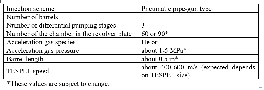
Tracer-encapsulated solid pellet (TESPEL) system
The TESPEL system to provide the known amount of impurities into the core or edge plasmas of JT-60SA for a quantitative study of the impurity transport will be prepared. As a tracer impurity, any element can be embedded if it is solid, and allowed by applicable regulations. The typical amount of the impurity injected into the plasma will be around 3×10¹⁸ particles. In the case of tungsten (W), the tungsten ion density in the typical JT-60SA plasma (Vplasma =133 m3) is expected as 2.3×10¹⁶ m-3 and consequently the ratio to the bulk ion is estimated as 0.028 % with the averaged bulk ion density of 8×10¹⁹ m-3. The electron density sourced from the tungsten injected by the TESPEL is expected as 1.7×10¹⁸ m-3 and consequently the ratio to the bulk electron is estimated as 2.1 % with the averaged bulk electron density of 8×10¹⁹ m-3. The typical outer diameter of the TESPEL, which can contain the impurity with the particle number of 3×10¹⁸ is 1.2 mm. In this case, for the JT-60SA plasma with the averaged bulk density of 8×10¹⁹ m-3, the carbon contamination by the TESPEL is estimated as 0.4 %, and the electron density will be increased totally by 4.9 %.
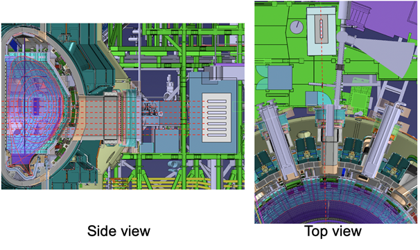
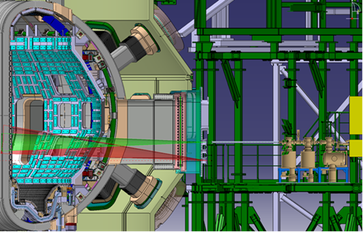
The TESPEL injector employs a pneumatic pipe-gun method. The TESPELs are stored in the small chambers of a revolver plate in the TESPEL storage disk. The TESPEL in the small chamber, which is aligned with the barrel, is accelerated by a high-pressured (about 1-5 MPa) helium (He) (or hydrogen (H)) gas, and the resulting TESPEL speed is expected to about 400-600 m/s (depending on the TESPEL size, less speed with the smaller TESPEL) with the TESPEL diameter of 1.2 mm and the barrel length of about 0.5 m. The acceleration gas will be evacuated by a differential pumping system. As shown in Figure 1, the TESPEL injector is installed at the P9 horizontal port (a green-coloured shaded area shows the expected area of TESPEL penetration path). In order to evaluate the penetration depth of the TESPEL and the deposition location of the tracer impurities in the JT-60SA plasmas, optical systems for the observation of TESPEL ablation from behind is installed at the same P9 port (a red-coloured shaded area of Figure 1 shows an expected field of view (FOV) of one of the ports for monitoring the TESPEL ablation). The ablation emissions of the shell and tracer impurities from the TESPEL are measured using filtered photodetectors (e.g., photomultiplier tubes) with a high time resolution of several hundreds of kHz. The TESPEL speed is measured by means of a time-of-flight method with two laser gate systems in the TESPEL injector. By the combination of these two measurements, the penetration depth and deposition location of the TESPEL can be evaluated with the spatial resolution of around 0.2 cm. The specification of the TESPEL injector is summarized in Table 1.
Fast Ion Loss Detectors
In order to identify plasma fluctuations which cause losses of fast ions, Fast Ion Loss Detectors (or FILD) are required. The detectors provide velocity-space measurements of escaping ions with a temporal resolution in the order of milliseconds.
The detectors must be very close to the plasma, in an area with extreme heat loads very close to the plasma when operating. In order to avoid damage they are mounting on a retractable arm, which moves towards the plasma for short periods when measurements are being taken.
The detectors themselves are scintillator based, emitting light when hit by fast ions. The light emitted by the scintillators will be collected by the light acquisition system, where it will be recorded by a fast visible camera.