
Phase I Plasma Diagnostics
Some limited diagnostics will be prepared for IC for machine protection and confirmation of the controllability of plasma. They are summarized in Table 1.
| Diagnostics | Section | Port/Location |
| CO2 Laser interferometer (tangential), Visible spectroscopy (tangential) | P1 and P8 | Horizontal |
| Soft X-ray detector arrays | P14 | Horizontal |
| Visible TV cameras (+ two light guide) | P15 | Horizontal |
| EDICAM | P18 | Horizontal |
| Langmuir probes | P2, P8 and P14 | upper divertor |
Laser interferometer (tangential)
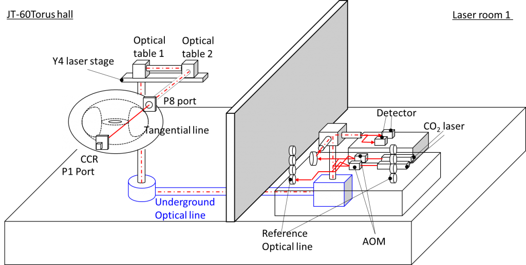
The tangential CO2 laser interferometer is used for measurement of line-integrated electron density along a tangential chord. The measured line-integrated density will be used not only for plasma physics, but also for real-time feedback of plasma control. Its major components, e.g. lasers, Acousto-Optic modulators (AOM) and detectors, will be installed in “Laser Room 1” where the FIR laser system for an interferometer of JT-60U was installed. The apparatus in the torus hall, e.g. vacuum windows and laser transmission optics, are newly fabricated to match JT-60SA. Figure 1 shows the system configuration of CO2 tangential interferometer/polarimeter. Figure 2 shows a schematic view of the system. The target specification is shown in Table 2.
| temporal resolution | 5 ms (offline data) and 1 ms (for realtime feedback) |
| density resolution | ~2×10¹⁹ m-2 (5 ms) and ~0.5×10¹⁹ m-2 (1 ms) |
| Channels | 1 (tangential, P8-P1) |
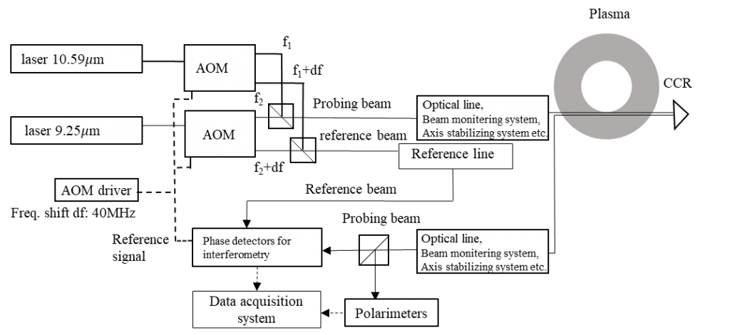
The CO2 laser interferometer mainly consists of two lasers, two AOMs, optical line, reference line, two phase detectors for interferometry, two polarimeters and a data acquisition system. Wavelengths of two-color lasers are 10.59 mm and 9.25 mm, respectively. Probing beam, which is not diffracted by the AOM, is transmitted and injected into JT-60SA plasma. Here, an amount of frequency shift with the AOM is 40MHz. The probing beam returned from the plasma is split to the phase detectors for interferometry and the polarimeters. Other laser beam, diffracted by the AOM, is transmitted to the reference line in laser room 1. In the case of interferometry, the probing beam and the reference beam are superimposed to generate modulated beat signal with JT-60SA plasma for each wavelength. Phase difference between reference signal from AOM driver and the modulated beat signal is measured with each phase detector. In the data acquisition system, effect of vibration of optical instruments in the transmission line on the phase difference will be corrected simultaneously with data acquisition. In the case of polarimeters, the PEM system on JT-60U will be utilized for JT-60SA.
Visible spectroscopy
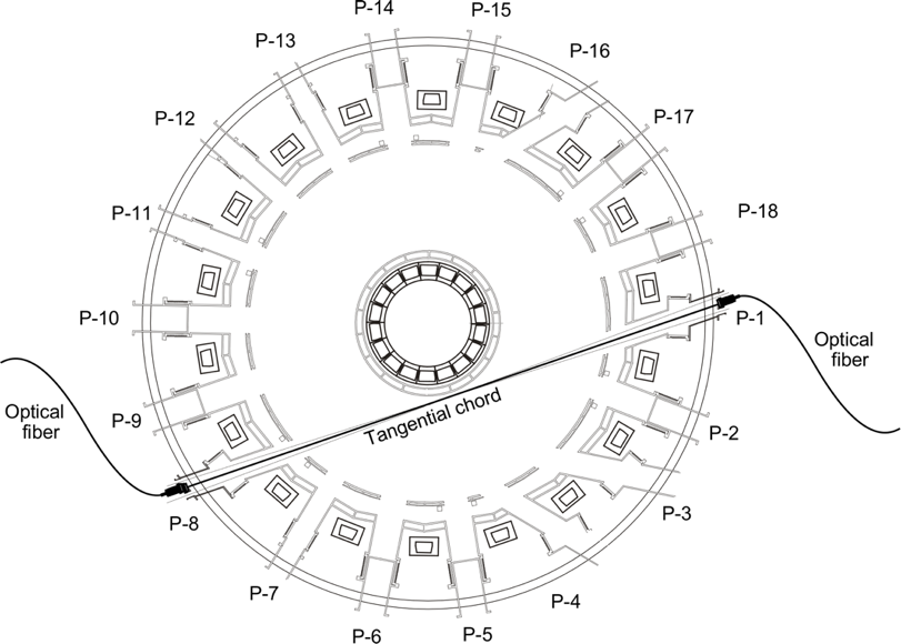
The purpose of this system is to measure the intensities of Ha emission, Bremsstrahlung emission and other spectral lines. The viewing chord is tangential between the P1 horizontal port and the P8 horizontal port as shown in Figure 3. Two identical optical systems, each of which consists of a vacuum window (with an effective diameter of 43 mm), a lens (with a focal length of 100 mm) and a bundle of 19 optical fibers (core and clad diameter of 200 mm and 250 mm, respectively and a numerical aperture of 0.2), are installed at the P1 and the P8 port. An image of the central optical fiber is mapped onto the vacuum window of the other optics system (distance ~ 13700 mm) with a diameter of less than 40 mm. The layout of the optic allows to calibrate the sensitivity of the whole spectroscopic system including the vacuum window without in-vessel work: a standard light source just outside the vacuum window can be used to calibrate the sensitivity of the other optical system through the two vacuum windows. In addition, simultaneous measurement from the two ports enables to improve the accuracy through comparison and provide redundancy.
Emission from the plasma through the optic system is transmitted to the diagnostic room. In the diagnostics room, photomultipliers detect and filter the emitted light filtered with interference filters with a bandpass width of 1 nm and a transmittance peak wavelengths of 656.1 nm (Ha), 523.2 nm (Bremsstrahlung) and 657.8 nm (C II, for example) with a time resolution of 50ms. Some of the optical fibers are connected to a spectrometer with a spectral band ranging from 400 nm to 800 nm with a time resolution of 300ms. The photomultipliers, the interference filters, the spectrometer and the data acquisition system used in JT-60U will be reused. Table 3 shows the specification of the system.
| Viewing chord | Tangential from P1 horizontal to P8 horizontal port |
| Optical fibre | 19 fibres x 2 arrays (P1 and P8), Core 200 mm, clad 250 mm, N/A 0.2 |
| Lens | Achromatic, f = 100 mm, diameter 50 mm |
| Image | Less than 40 mmf at 13700 mm from the lens |
| Photomultiplier | 656.1 nm (Ha), 523.2 nm (Brems), 657.8 nm (C II), bandpass width ~ 1 nm, time resolution 50 ms |
| Spectrometer | Spectral band 400-800 nm, time resolution 300 ms, back-illuminated CCD camera |
Soft X-ray detector arrays
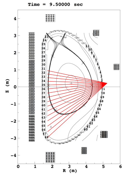
The purpose of this system is to observe the last closed flux surface (LCFS), the magnetic axis and the electron temperature profile by measuring the intensities of soft X-ray emission through a pinhole. For IC, only soft X-ray detector arrays is available for the electron temperature profile measurement. The system consists of two detectors. Each detector has an Absolute X-ray and UV (AXUV) sensor, a pre-amplifier and thin beryllium films. The detectors are put on the end of a port plug and the port plug is inserted at the P14 horizon port. Both detectors have a similar measuring range set at a poloidal angle of ~15 degrees downwards which allows to measure the lower half of the plasma as shown in Figure 4. The outputs of the pre-amplifiers are transferred to digitizers installed inside the electromagnetic shield box located at the PIG room (underground floor). Since Be films work as band pass filters, the electron temperature can be evaluated by the ratio of the intensities from two detectors with different film thickness. Table 4 shows the specification of the system.
| Location | P14 horizontal port |
| Detector array | AXUV 16 channels x 2 arrays |
| Filter | Thin film of beryllium 2 kinds of thickness for Te profile measurement (TBD) |
| Image size | Less than 40 mmf at 13700 mm from pinhole (Diameter ~1.5 mmf, TBD) |
| Time resolution | Maximum sampling frequency: 1MHz |
| Water cooling | For the cooling of detectors and amplifiers parameters: tbd. |
| Vacuum flange | f500 mm, flat surface |
The visible TV diagnostics is located in port P15 (periscopes) and P18 (EDICAM), having a tangential co- or counter-view into the torus as shown in Figure 5. The field-of-view (FoV) for each viewing chord is in the order of 80°, covering a wide area of the vacuum vessel, such as inner wall and upper divertor region. The main role of the visible TV diagnostic is to monitor the Plasma Wall Interactions (PWIs) at the divertor, limiter and first wall. The light-guide systems will also be equipped under each port-plug for illuminating inside the vacuum vessel without plasma emission, using a fiber optics connected to the metal halide lamp (375 W). The specifications of the visible TV system are shown in Table 5.
| Periscope | |
| Camera type [Resolution] | Analog colour (NTSC) [768(H)×494(V)] |
| Field-of-view | ~80° |
| Depth-of-field | 3-8 m |
| Viewing direction | tilted by +/- 40° to port plug axis |
| Temporal resolution | 30 Hz |
| Spatial resolution | 4~5 cm |
| Wavelength range | 520 – 720 nm |
| Mechanical protection | Double windows having sapphire (6mm thickness) for cover glass |
| Heat load tolerance | max. 25 kW/m2 for 100 s, inertia cooling |
| Vacuum flange | f450 mm, flat surface |
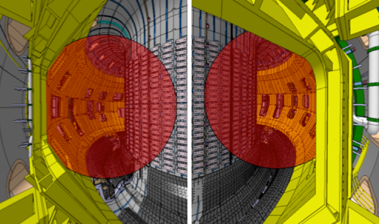
Event Detection Intelligent Camera (EDICAM)
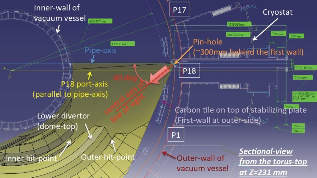
The EDICAM diagnostic is located in port P18, having a tangential view into the torus (see Figure 6). Equipped with wide-angle optics, the field-of-view (FoV) is in the order of 80°, thus the camera view can cover about 1/5 of the plasma vessel. A fast wide-angle visible video diagnostic system, based on the Event Detection Intelligent Camera (EDICAM) can also measure, in addition to recycling and impurity influx, the visible light emission associated with fast phenomena such as plasma start up, disruptions, gas injection or even edge filaments.
The EDICAM camera is based on a special 1.3 Mpixel CMOS chip that allows non-destructive readout of the sensor contents, independently of the exposure cycle, and a very flexible region-of-interest (ROI) handling. Due to its unique features, the EDICAM is capable to handle up to six independent ROIs simultaneously, that can be freely positioned over the sensor, allowing for the monitoring of critical areas with good time resolution. The specifications of the EDICAM system are shown in Table 6.
| Field-of-view | 80° |
| Depth-of-field | 3-8 m |
| Viewing direction | tilted by 40° to port plug axis |
| Temporal resolution | 100 Hz |
| Spatial resolution | 1-2 cm |
| Wavelength range | 520 – 720 nm |
| Mechanical protection | steel cover plate with pin-hole (entrance pupil) and shutter |
| Heat load tolerance | max. 55 kW/m2 for 100 s, water cooling for pin-hole |
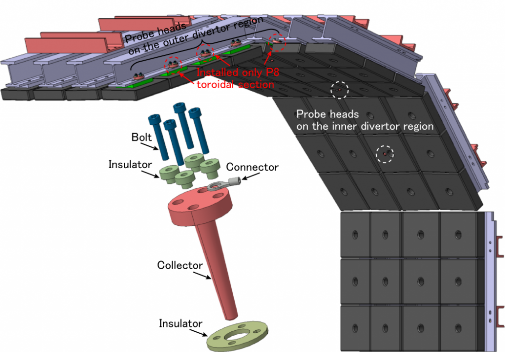
Langmuir probes (upper divertor)
The primary purpose of the Langmuir probes is the detection of the divertor leg during its sweeping. The position of the divertor leg evaluated from the Langmuir probes is compared with that evaluated by the Plasma Control System (PCS) or equilibrium solver (Meudas). This comparison shall confirm the controllability of the plasma position and shape. To evaluate the position of the divertor leg, four Langmuir probe heads (two is the inner divertor region and two the outer divertor region) are installed at the P2, P8 and P14 toroidal sections of the upper divertor. Additional three heads are installed around the outer divertor region at the P8 toroidal section to evaluate the position of the divertor leg for various plasma configurations. The Langmuir probe head is mounted on the structure of the upper divertor as shown in Figure 7. The Langmuir probe head is composed of a corrector, insulators, a connector and bolts. A mineral insulated (MI) cable is connected to the collector with the connector. The Langmuir probe head on the plasma side is dome shaped with a dimeter and a height of 6.0 mm and 1.2 mm, respectively. A DC voltage is supplied by a power supply installed in the tokamak hall and passed by the MI cables through vacuum feedthroughs installed on the P1, P8, P14 horizontal ports. An ion saturation current (Iis) for detection of the divertor leg position is measured at a time resolution of ≤ 50ms with the data acquisition system installed on the tokamak hall. Evaluation of electron temperatures (Te), electron densities (ne) and floating potential (Vf) can be evaluated by sweeping the applied voltage. The specifications of the Langmuir probes are shown in Table 7.
| Location and number of probes | P2 and P14: 2 in inner divertor region and 2 in outer divertor region P8: 2 in inner divertor region and 5 in outer divertor region |
| Time resolution | Ion saturation current mode (Iis): 50 ms Voltage sweep mode (Te, ne and Vf): 1 ms |
Phase I diagnostic gallery


